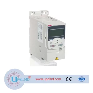
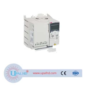
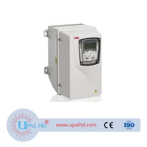
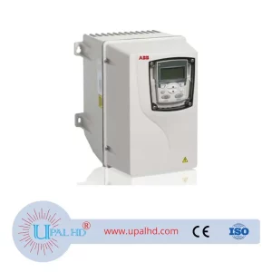
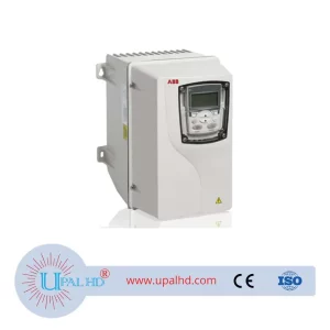
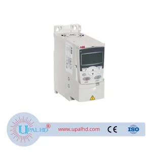
ATV212WU75N4 inverter, 7.5kw ATV212 spot free shipping
- Name: ATV212WU75N4 inverter, 7.5kw ATV212 spot free shipping
- Brand: Schneider
- Model: ATV212WU75N4
- MOQ. : 1
- Warranty Time : 1 Year
- Certificates: ISO9001
- Price:
- Contact Person: Ms. Ma Meiying
- Email: sales@upalhd.com
- Email: sales.upalhd@hotmail.com
- Mobile-1: +86-16622133544
- Phone-2: +86-16602136043
Share to:
- Contact Peroson: Ms. Raihana
- Email: sales@upalhd.com
- Email: salse.upalhd@hotmail.com
- Phone-1: +86-16602136043
- Phone-2: +86-15557972300
Aditional Informations
PRODUCT INFORMATION OF SCHNEIDER ATV212WU75N4 inverter, 7.5kw ATV212 spot free shipping
| Device short name | ATV212 |
|---|---|
| Product destination | Asynchronous motors |
| Network number of phases | 3 phases |
| motor power kW | 7.5 kW |
| motor power hp | 10 hp |
| Supply voltage limits | 323…528 V |
| supply frequency | 50…60 Hz – 5…5 % |
| line current of ATV212WU75N4 inverter | 11.7 A at 480 V 14.7 A at 380 V |
| Range of product | Altivar 212 |
| Product or component type | Variable speed drive |
| Product specific application | Pumps and fans in HVAC |
| Communication port protocol | BACnet Modbus LonWorks METASYS N2 APOGEE FLN |
| [Us] rated supply voltage | 380…480 V – 15…10 % |
| EMC filter | Class C2 EMC filter integrated |
| IP degree of protection | IP55 |
| apparent power | 12.2 kVA at 380 V |
| continuous output current | 16 A at 380 V 16 A at 460 V |
| maximum transient current | 17.6 A for 60 s |
| Speed drive output frequency | 0.5…200 Hz |
| speed range of ATV212WU75N4 inverter | 1…10 |
| speed accuracy | +/- 10 % of nominal slip 0.2 Tn to Tn |
| local signalling | 1 LED (red) for DC bus energized |
| Output voltage | <= power supply voltage |
| Isolation of ATV212WU75N4 inverter | Electrical between power and control |
| type of cable of ATV212WU75N4 inverter | Without mounting kit: 1 wire(s)IEC cable at 45 °C, copper 90 °C / XLPE/EPR Without mounting kit: 1 wire(s)IEC cable at 45 °C, copper 70 °C / PVC With UL Type 1 kit: 3 wire(s)UL 508 cable at 40 °C, copper 75 °C / PVC |
| electrical connection | VIA, VIB, FM, FLA, FLB, FLC, RY, RC, F, R, RES: terminal 2.5 mm² / AWG 14 L1/R, L2/S, L3/T: terminal 16 mm² / AWG 6 |
| tightening torque | 0.6 N.m (VIA, VIB, FM, FLA, FLB, FLC, RY, RC, F, R, RES) 2.5 N.m, 22 lb.in (L1/R, L2/S, L3/T) |
| supply of ATV212WU75N4 inverter | Internal supply for reference potentiometer (1 to 10 kOhm): 10.5 V DC +/- 5 %, <10 A, protection type: overload and short-circuit protection Internal supply: 24 V DC (21…27 V), <200 A, protection type: overload and short-circuit protection |
| sampling duration | 2 ms +/- 0.5 ms F discrete 2 ms +/- 0.5 ms R discrete 2 ms +/- 0.5 ms RES discrete 3.5 ms +/- 0.5 ms VIA analog 22 ms +/- 0.5 ms VIB analog |
| response time | FM 2 ms, tolerance +/- 0.5 ms for analog output(s) FLA, FLC 7 ms, tolerance +/- 0.5 ms for discrete output(s) FLB, FLC 7 ms, tolerance +/- 0.5 ms for discrete output(s) RY, RC 7 ms, tolerance +/- 0.5 ms for discrete output(s) |
| accuracy of ATV212WU75N4 inverter | +/- 0.6 % (VIA) for a temperature variation 60 °C +/- 0.6 % (VIB) for a temperature variation 60 °C +/- 1 % (FM) for a temperature variation 60 °C |
| linearity error | VIA: +/- 0.15 % of maximum value for input VIB: +/- 0.15 % of maximum value for input FM: +/- 0.2 % for output |
| analogue output type | FM switch-configurable voltage 0…10 V DC, impedance: 7620 Ohm, resolution 10 bits FM switch-configurable current 0…20 mA, impedance: 970 Ohm, resolution 10 bits |
| discrete output type | Configurable relay logic: (FLA, FLC) NO – 100000 cycles Configurable relay logic: (FLB, FLC) NC – 100000 cycles Configurable relay logic: (RY, RC) NO – 100000 cycles |
| minimum switching current | 3 mA at 24 V DC for configurable relay logic |
| maximum switching current | 5 A at 250 V AC on resistive load – cos phi = 1 – L/R = 0 ms (FL, R) 5 A at 30 V DC on resistive load – cos phi = 1 – L/R = 0 ms (FL, R) 2 A at 250 V AC on inductive load – cos phi = 0.4 – L/R = 7 ms (FL, R) 2 A at 30 V DC on inductive load – cos phi = 0.4 – L/R = 7 ms (FL, R) |
| discrete input type | F programmable 24 V DC, with level 1 PLC, impedance: 4700 Ohm R programmable 24 V DC, with level 1 PLC, impedance: 4700 Ohm RES programmable 24 V DC, with level 1 PLC, impedance: 4700 Ohm |
| discrete input logic | Positive logic (source) (F, R, RES), <= 5 V (state 0), >= 11 V (state 1) Negative logic (sink) (F, R, RES), >= 16 V (state 0), <= 10 V (state 1) |
| dielectric strength | 3535 V DC between earth and power terminals 5092 V DC between control and power terminals |
| insulation resistance | >= 1 mOhm 500 V DC for 1 minute |
| frequency resolution | Display unit: 0.1 Hz Analog input: 0.024/50 Hz |
| Communication service | Write multiple registers (16) 2 words maximum Read device identification (43) Write single register (06) Time out setting from 0.1 to 100 s Read holding registers (03) 2 words maximum Monitoring inhibitable |
| option card of ATV212WU75N4 inverter | Communication card for LonWorks |
| Functionality | Mid |
| Specific application | HVAC |
| Discrete output number | 2 |
| Analogue input number | 2 |
| analogue input type | VIA switch-configurable voltage: 0…10 V DC 24 V max, impedance: 30000 Ohm, resolution 10 bits VIB configurable voltage: 0…10 V DC 24 V max, impedance: 30000 Ohm, resolution 10 bits VIB configurable PTC probe: 0…6 probes, impedance: 1500 Ohm VIA switch-configurable current: 0…20 mA, impedance: 250 Ohm, resolution 10 bits |
| Analogue output number | 1 |
| Physical interface | 2-wire RS 485 |
| Connector type | 1 open style 1 RJ45 |
| Transmission rate | 9600 bps or 19200 bps |
| Transmission frame | RTU |
| Number of addresses | 1…247 |
| Data format of ATV212WU75N4 inverter | 8 bits, 1 stop, odd even or no configurable parity |
| Type of polarization | No impedance |
| Asynchronous motor control profile | Voltage/frequency ratio, automatic IR compensation (U/f + automatic Uo) Flux vector control without sensor, standard Voltage/frequency ratio, 5 points Voltage/frequency ratio, 2 points Voltage/frequency ratio – Energy Saving, quadratic U/f |
| Torque accuracy | +/- 15 % |
| transient overtorque | 120 % of nominal motor torque +/- 10 % for 60 s |
| Acceleration and deceleration ramps | Linear adjustable separately from 0.01 to 3200 s Automatic based on the load |
| Motor slip compensation | Automatic whatever the load Adjustable Not available in voltage/frequency ratio motor control |
| switching frequency | 6…16 kHz adjustable 12…16 kHz with derating factor |
| Nominal switching frequency | 12 kHz |
| Braking to standstill | By DC injection |
| Network frequency | 47.5…63 Hz |
| Prospective line Isc | 22 kA |
| protection type | Overheating protection: drive Thermal power stage: drive Short-circuit between motor phases: drive Input phase breaks: drive Overcurrent between output phases and earth: drive Overvoltages on the DC bus: drive Break on the control circuit: drive Against exceeding limit speed: drive Line supply overvoltage and undervoltage: drive Line supply undervoltage: drive Against input phase loss: drive Thermal protection: motor Motor phase break: motor With PTC probes: motor |
| Width of ATV212WU75N4 inverter | 230 mm |
| Height of ATV212WU75N4 inverter | 340 mm |
| Depth of ATV212WU75N4 inverter | 208 mm |
| Product weight | 10.95 kg |
| pollution degree | 3 conforming to IEC 61800-5-1 |
| IP degree of protection | IP55 conforming to EN/IEC 61800-5-1 IP55 conforming to EN/IEC 60529 |
| vibration resistance | 1.5 mm (f= 3…13 Hz) conforming to EN/IEC 60068-2-6 1 gn (f= 13…200 Hz) conforming to EN/IEC 60068-2-8 |
| shock resistance | 15 gn for 11 ms conforming to IEC 60068-2-27 |
| environmental characteristic | Classes 3C1 conforming to IEC 60721-3-3 Classes 3S2 conforming to IEC 60721-3-3 |
| noise level of ATV212WU75N4 inverter | 55 dB conforming to 86/188/EEC |
| operating altitude | 1000…3000 m limited to 2000 m for the Corner Grounded distribution network with current derating 1 % per 100 m <= 1000 m without derating |
| relative humidity | 5…95 % without condensation conforming to IEC 60068-2-3 5…95 % without dripping water conforming to IEC 60068-2-3 |
| ambient air temperature for operation | -10…40 °C (without derating) 40…50 °C (with derating factor) |
| Operating position | Vertical +/- 10 degree |
| Product certifications | CSA C-Tick NOM 117 UL |
| Marking of ATV212WU75N4 inverter | CE |
| Standards of ATV212WU75N4 inverter | EN 61800-3 environments 2 category C1 IEC 61800-5-1 IEC 61800-3 environments 1 category C2 EN 61800-3 category C3 EN 61800-3 environments 1 category C3 EN 61800-3 category C2 IEC 61800-3 environments 2 category C2 IEC 61800-3 category C3 IEC 61800-3 environments 2 category C1 IEC 61800-3 category C2 EN 61800-5-1 EN 61800-3 environments 2 category C2 EN 61800-3 environments 1 category C1 IEC 61800-3 environments 1 category C1 EN 61800-3 environments 2 category C3 EN 61800-3 EN 55011 class A group 1 EN 61800-3 environments 1 category C2 IEC 61800-3 environments 2 category C3 IEC 61800-3 IEC 61800-3 environments 1 category C3 |
| Assembly style | With heat sink |
| electromagnetic compatibility | Electrostatic discharge immunity test level 3 conforming to IEC 61000-4-2 Radiated radio-frequency electromagnetic field immunity test level 3 conforming to IEC 61000-4-3 Electrical fast transient/burst immunity test level 4 conforming to IEC 61000-4-4 1.2/50 µs – 8/20 µs surge immunity test level 3 conforming to IEC 61000-4-5 Conducted radio-frequency immunity test level 3 conforming to IEC 61000-4-6 Voltage dips and interruptions immunity test conforming to IEC 61000-4-11 |
| Regulation loop of ATV212WU75N4 inverter | Adjustable PI regulator |
| Ambient air temperature for storage | -25…70 °C |
FAQ ( frequently ask questions )
A: inquiry→quotation→confirm→send PI→make the payment→arrange the parts→delivery→receive the parts
A: By sea to your nearest port
By air to your nearest airport
By express (DHL,UPS,FEDEX,TNT,EMS)to your door
When your order shipping out . we will provide you a tracking number. then you can know clearly the status of the goods
A: Motsly parts we have stock before you want to book with us pls email us and confirm the delivery time and price. Usually 1-5 working days.
| DHL | Around 3-5 working days |
|---|---|
| FedEx | Around 3-5 working days |
| UPS/TNT | Around 6-8 working days |
| EMS | Around 10-15 working days |
| AIR | Around 5-7 working days |
| SEA | Around 15-30 working days |
A: Of course, common products are allowed to be exchanged as long as you pay the freight and custom cost
A: Yes, we have warranty for our parts. 3 months for PCB, 2 years for original roller and other roller, 3-5 years for COMI roller and 1 year for Yaskawa inverter. Please contact us to get more information for other products
A: You can send it back to repair ,but the freight and repair charge will be paid by you.
A: TT, Western Union, Pay pal, You can choose a convinient way for you .
Kindly contact our staff to get more answers. Thanks for your cooperation!!!”